Understanding depth perception in human vision provides the foundation for developing 3D imaging systems that mimic natural spatial awareness. Depth perception is the ability to interpret spatial relationships and determine how far or close objects are relative to the observer. It forms the basis for 3D imaging and 3D camera technologies, which emulate this perception through optics and computational models.
In this blog, you’ll get expert insights on how depth perception works, the different types of depth sensing cameras and more.
First, let’s understand the cues involved.
Types of Depth Perception Cues
Humans rely on two cues for depth perception: binocular cues and monocular cues.
1) Binocular cues
Binocular cues work by using both eyes to gather depth information. This type of perception is critical for understanding distances, shapes, and the relative positioning of objects in a three-dimensional space.
Let’s now understand the three principles involved:
Stereopsis (or binocular parallax)
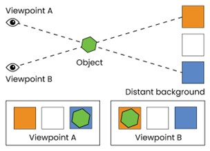
It refers to the subtle differences in images perceived by the left and right eyes due to their spatial separation, which is called parallax. The brain processes these differences to generate a sense of depth. When an object is observed from two slightly different perspectives (as captured by the two eyes), its position appears to shift against the background as shown below.
 Figure 1: Binocular Parallax
The stereopsis principle is applied in devices like stereoscopic cameras and 3D cinema projection systems, where two separate views are combined to create a perception of depth.
Convergence
It is the inward movement of the eyes when focusing on a nearby object. The brain uses the degree of muscular effort involved in eye movement to estimate proximity. So, the extent to which the eyes turn inward provides information about the object’s distance. Convergence is mimicked in certain optical systems that need accurate focus adjustments for near-field subjects.
Shadow stereopsis
It involves the interpretation of shadows as depth indicators. While not a primary binocular cue, this enhances depth perception by adding layers of information about object orientation and distance. So, when shadows cast by an object shift differently between the left and right eyes, this differential can be interpreted to calculate spatial depth.
2) Monocular cues
Monocular cues derive depth information from a single eye. These help distant objects or in situations where binocular vision is unavailable. Monocular cues are integral to many imaging systems that simulate depth perception.
Let’s look at the components of monocular cues:
Motion parallax
Motion parallax describes the apparent relative motion of objects when the observer moves. Objects closer to the observer move faster than those farther away. Hence, as the viewpoint changes, objects at varying distances shift relative to one another, providing critical depth information even with one eye closed.
 Figure 2: Motion Parallax
Motion parallax is the basis of applications like depth sensing in augmented reality AR or VR.
Occlusion
Occlusion occurs when one object partially obscures another, indicating that the obscured object is farther away. So, the brain automatically interprets overlapping objects as having distinct spatial positions. Many 3D imaging systems use occlusion-based algorithms for rendering realistic scenes, especially in layered visuals.
Familiar size
The brain leverages prior knowledge of an object’s size to estimate its distance. For example, a smaller-than-expected image of a known object suggests that it is farther away.
Texture gradient
As objects recede into the distance, their texture becomes denser and less distinguishable. It helps establish depth perception for continuous surfaces.
Lighting and shading
Light and shadow interactions offer clues about the depth and orientation of objects. Their position, shape, and intensity change with the light source and object position, providing valuable depth information.
Role of Parallax in 3D Imaging
Simply put, parallax makes it possible to create depth for 3D imaging systems. It helps capture and analyze the disparity in the apparent position of objects from different viewpoints. That way, cameras and imaging devices can easily reconstruct spatial data.
Types of Depth Sensing Cameras
1) Stereo vision cameras
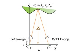
Stereo vision cameras operate on principles akin to human binocular vision, where two lenses, separated by a fixed baseline, capture slightly offset images of the same scene. The system uses triangulation to compute depth by analyzing the disparities between the two images. This disparity is inversely related to the object’s distance from the cameras; closer objects result in larger disparities, leading to more accurate depth estimates. The following diagram illustrates how stereo cameras use baseline (b), focal length (f), and image disparities (ul, ur) to calculate depth (Zp) for a point P in 3D space

Figure 3: Principles behind Stereo Camera Depth Sensing
A major factor in stereo vision is the baseline b, which impacts depth accuracy. Increasing the baseline enhances precision but introduces challenges, such as missing information for objects visible to only one camera. Even in advanced commercial stereo setups, the images captured by the two cameras may not be perfectly aligned. Such misalignment necessitates calibration to compute two sets of parameters.
- Extrinsic parameters, which describe the spatial relationship between the cameras
- Intrinsic parameters, which detail the optical properties of each lens, including focal length and distortion.
Manual Disparity Calculation

Figure 4: Stereo Vision – Depth Calculation Using Image Disparities
Theoretically formula for calculating depth:
z =(f *m*b)/d
where
f – focal length ,
b – base line,
m – pixels per unit length
d- disparity
Example Calculation:
f = 0.0028 m, b = 0.12 m
Sensor size =1/3“ = 1/3 * 0.0254 =0.00847 m
m = sqrt(2208 ^2 + 1242 ^2) /0.00847 m = 299095.985 m
Each camera resolution: 2208*124
Pixel Coordinates:
Pixel co ordinate at first image (1340,663)
Pixel co ordinate of second image (3515,663)
Disparity Calculation:
Subtracting identical pixel from concatenated image (3515-2208) =1307
Disparity value between identical pixel is 1340 -1307 = 33 pixels
Depth Calculation:
Applying the value to the formula
z = (0.0028 * 299095.985 * 0.12) /33 = 3.04 m
Stereo vision cameras are used in autonomous vehicles and robots, as well as industrial automation systems. They are valued for their simplicity and ability to generate high-resolution depth maps, though they require careful calibration and are most effective at closer ranges.
2) Time-of-Flight (ToF) cameras
Time-of-flight cameras take a different approach by evaluating the exact time the light takes to travel to an object and then back. It calculates depth using the formula
d= cΔT/2
- c is the speed of light
- ΔT is the time delay between the emission and reception of the light pulse.
ToF systems are known for their precision and suitability for dynamic scenes.
A typical ToF camera setup comprises three components:
- Sensor module
- Light source
- Depth sensor

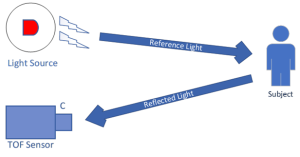
Figure 5: Illustration of ToF Camera measuring Depth
The sensor module measures the reflected light, while the light source, often operating in the infrared spectrum, illuminates the scene. The depth sensor captures data for each pixel in the scene, generating a depth map. This depth map can be visualized as a three-dimensional point cloud, where each point represents a specific spatial location.
ToF cameras are perfect for applications requiring rapid depth measurements, such as gesture recognition, augmented reality systems, and autonomous navigation. While their ability to capture depth information for every pixel in real time, their performance may degrade in highly reflective or absorptive surfaces that demand algorithmic corrections.
3) Structured Light Cameras
Structured light cameras use a method where the scene is illuminated with a known geometric pattern, such as a grid or stripe. The pattern is projected onto the surface, and the distortions caused by the surface geometry are analyzed to compute depth. It ensures highly accurate depth measurements in controlled environments.
Unlike stereo or ToF cameras, structured light systems calculate depth sequentially, illuminating one point at a time across a two-dimensional grid. While this provides detailed depth information, the sequential nature of the process limits its speed. Consequently, these cameras are not suitable for dynamic scenes and are best used in applications like quality control in manufacturing or static 3D scanning.
A big advantage of structured light cameras is their ability to provide high depth accuracy in well-lit, static conditions. However, they are sensitive to environmental factors such as ambient light and object reflectivity, which can affect data reliability.
e-con Systems Offers Cutting-Edge 3D Cameras
Since 2003, e-con Systems has been designing, developing, and manufacturing OEM camera solutions. Our DepthVista camera series features the latest 3D cameras based on Time-of-Flight technology.
These ToF cameras can operate within the NIR spectrum (850nm/940nm) and deliver high-quality 3D imaging for indoor or outdoor environments. They are capable of built-in depth processing for providing real-time 2D and 3D data output, which makes them perfect for applications like autonomous robots, self-driving agricultural machinery, medical monitoring devices, and facial recognition systems.
e-con Systems’ DepthVista camera series supports interfaces like USB, MIPI, and GMSL2, and comes. They come with drivers and SDKs compatible with NVIDIA Jetson AGX ORIN/AGX Xavier platforms and X86-based systems.
To learn more, visit our 3D depth camera page.
e-con Systems also offers stereo vision camera solutions – Tara and TaraXL.
To see our full portfolio, use our Camera Selector.
If you need expert help integrating 3D cameras into your projects, please write to camerasolutions@e-consystems.com.

Prabu is the Chief Technology Officer and Head of Camera Products at e-con Systems, and comes with a rich experience of more than 15 years in the embedded vision space. He brings to the table a deep knowledge in USB cameras, embedded vision cameras, vision algorithms and FPGAs. He has built 50+ camera solutions spanning various domains such as medical, industrial, agriculture, retail, biometrics, and more. He also comes with expertise in device driver development and BSP development. Currently, Prabu’s focus is to build smart camera solutions that power new age AI based applications.


