

3D imaging technologies have revolutionized various industries, providing advanced capabilities in depth perception and spatial understanding. Among these technologies, Time-of-Flight (ToF) cameras stand out for their ability to capture depth information in real-time. Leveraging the principle of measuring the time taken for light to travel to and from objects in a scene, ToF cameras provide depth data with remarkable speed and accuracy. With features like high frame rates, wide dynamic range, and suitability for both indoor and outdoor environments, ToF cameras are well-suited for applications ranging from robotics and automotive to augmented reality and biometrics. However, despite their numerous advantages, ToF cameras are susceptible to certain artifacts, such as flying pixels, which can affect the quality of depth images. Understanding the factors contributing to flying pixels and implementing effective mitigation strategies are essential for optimizing the performance of ToF cameras and ensuring reliable depth sensing in various applications.
In this blog, we will uncover the concept of flying pixels, explore their impact on 3D imaging quality and discuss how to mitigate their effects in Time-of-Flight camera.
What is Flying Pixel?
Flying pixels are erroneous depth readings that manifest as false pixels in the 3D point cloud generated by ToF cameras. They often occur at depth discontinuities in the scene, particularly at object boundaries. The light from foreground and background may combine at the edges to produce intermediate erroneous depth values, leading to the appearance of ghost pixels. While not always evident in depth-mapped images, they become noticeable in 3D point clouds.
![]()
Side view of 3D point cloud showing flying pixels
Factors Contributing to Flying Pixels
Aperture Size
The size of the lens aperture determines the quantity of light reaching the sensor. This factor is pivotal in imaging system design. For instance, in low-light conditions, a larger lens aperture is recommended as it allows more photons to reach the sensor, thereby improving image brightness and quality. However, increasing the lens aperture also reduces the depth-of-field of a camera. It may also increase the likelihood of artifacts such as flying pixels, especially near object boundaries.
Conversely, a narrower aperture may limit the amount of light reaching the sensor, potentially reducing SNR and image quality. However, it may also mitigate the effects of flying pixels by reducing the influence of reflected IR light from certain angles.
Exposure or integration time
The pixels of Time-of-Flight (ToF) cameras require a certain amount of time to gather sufficient light from the observed scene, a parameter referred to as exposure or integration time (texp). During this period, the camera’s position and orientation, as well as the targets observed in the scene, ideally remain constant. However, any relative movement between the camera and the scene can result in the observation of light paths from different targets for each pixel during texp. This phenomenon can lead to an inaccurate estimation of depth at object boundaries, giving rise to motion artifacts and flying pixels.
Interference from Other IR Sources
Flying pixels may occur due to interference from other infrared (IR) sources, such as sunlight, IR rays emitted by other cameras operating at the same wavelength and frequency, or external devices emitting IR light of similar wavelengths. This interference can disrupt the operation of Time-of-Flight (ToF) cameras, impacting their ability to accurately perceive depth information and resulting in the occurrence of flying pixels.
Pixel Size
Another reason for flying pixels is that each pixel in the TOF sensor has a certain physical size. When the edge of an object is measured, a single pixel receives light reflected from both the foreground and background simultaneously. This results in the depth information from different distances being superimposed, leading to raw sensor data containing intermediate depths.
Impact of Flying Pixels on Embedded Vision Applications
Flying pixels, erroneous depth readings in 3D point clouds generated by Time-of-Flight (ToF) cameras, can significantly impact embedded vision applications. These applications encompass a wide range of systems and devices that utilize cameras and vision sensors for diverse tasks such as object detection, recognition, tracking, navigation, and more.
Autonomous Mobile Robots (AMRs), among the embedded vision applications, play critical roles in tasks ranging from delivery and patrol duties to telepresence and automated weeding autonomously. These robots often rely on embedded cameras to capture images of their surroundings, aiding in tasks such as obstacle detection and object recognition. The captured images and videos are typically processed by an edge processor to analyze them for intelligent decision-making.
The false depth data points or flying pixels can create inaccurate perception of the environment. Consequently, an AMR may perceive flying pixels as obstacles and make decisions based on this incorrect information, potentially avoiding paths that are actually free of obstacles.
While the removal of flying pixels may appear to result in a loss of data, it is crucial for ensuring the accuracy of AMR decision-making processes. Filtering out these erroneous pixels helps prevent AMRs from making incorrect decisions based on false obstacle detections. Thus, despite the potential loss of some data, the filtering of flying pixels is essential for maintaining the reliability and effectiveness of AMR operations in various environments.
Different approaches to remove Flying Pixels
We discussed several factors leading to inaccuracies in depth perception and potentially impacting the performance of applications relying on ToF camera data. It’s important to note that flying pixels are absent or minimal in scenarios characterized by uniform surfaces, such as a plain wall or floor.
Diverse filtering and post-processing techniques allow a TOF camera to reliably generate a 3D point cloud and improve performance in the presence of flying pixels. Here, we discuss some of the approaches that are employed to remove flying pixels and improve the reliability of 3D imaging systems:
1. Post-Processing Filters
Post-processing filters are software-based techniques applied to 2D raw depth images to remove flying pixels. One such approach is the Depth Discontinuity Filter, developed by e-con Systems, alongside other commonly used filters like the Median Filter.
a. Depth Discontinuity Filter
The Depth Discontinuity Filter, developed by e-con Systems, works based on the depth discontinuity of a pixel from its neighbors. If a pixel has a large variation in depth from its neighboring pixels, it is considered a flying pixel. This filter identifies and removes such pixels, improving the overall quality of the depth map.
 |
 |
|
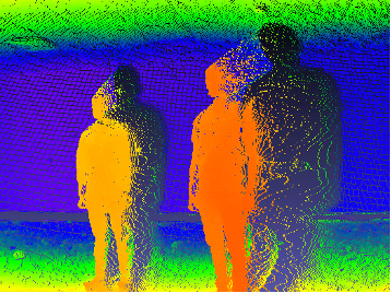
Without Depth Discontinuity Filter |
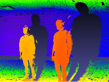
With Depth Discontinuity Filter |
The left image demonstrates the depth map generated without the Depth Discontinuity Filter, showcasing the flying pixels. In contrast, the right image illustrates the impact of applying the Depth Discontinuity Filter, resulting in a more accurate depth map with reduced flying pixels.
b. Median Filter
The Median Filter analyzes the depth values of neighboring pixels and excludes those that deviate significantly from the median value. This filter is based on a user-defined threshold, excluding pixels if the difference between the median value and the nearest neighbor exceeds the threshold. By mitigating outliers, the Median Filter effectively suppresses the influence of flying pixels on the final depth map.
Benefits of Post-Processing Filters
- Faster processing compared to hardware-based approaches.
- Effective suppression of flying pixels while retaining valid depth data.
- Can provide high quality images with less irrelevant data.
Challenges of Post-Processing Filters
- The frame rate of these filters depends on the host PC configuration.
- May not completely eliminate all flying pixels in complex scenes.
2. Hardware-Based Approaches
As flying pixels originate in the optical pipeline of ToF cameras, which includes various optical components and processes responsible for light collection and processing, modifying these components requires careful consideration to maintain overall light throughput and signal-to-noise ratio.
Hardware-based approaches involve modifications to the camera’s optical system or sensor design to reduce flying pixels. One such approach is the Mask TOF method.
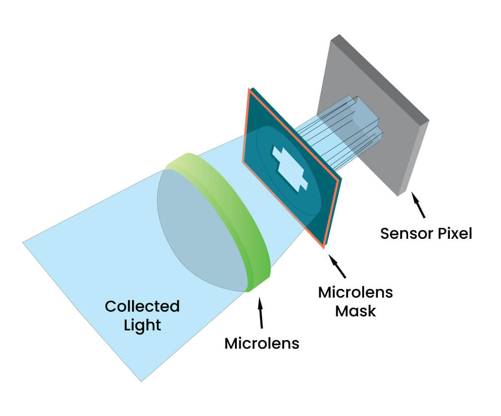
Mask TOF
Mask TOF augments the camera pipeline by inserting a microlens mask between the sensor pixel and its microlens. This mask selectively blocks incident light paths, allowing each pixel to have its own custom aperture. By reducing stray light paths, Mask TOF effectively reduces flying pixels and improves depth sensing accuracy.
 Advantages of Mask TOF
- Provides custom aperture configurations for each pixel, reducing flying pixels.
- Offers improved depth sensing accuracy without sacrificing overall light throughput.
Challenges of Mask TOF
- Requires hardware modifications, making it less practical for some applications.
- Filtered results may not be as effective as software-based approaches in all scenarios.
Both software-based and hardware-based approaches play a crucial role in removing flying pixels from ToF camera data. While post-processing filters offer fast and efficient removal of flying pixels, hardware-based approaches provide more tailored solutions but may require significant modifications to camera hardware.
We hope this blog provided a comprehensive understanding of Time-of-Flight cameras and the methods employed to address flying pixel issues.
e-con Systems’ DepthVista ToF Series
e-con Systems has designed and manufactured the DepthVista ToF series with several factors in mind, including optical calibration, temperature drifts, artifacts, flying pixels, VCSEL pulse timing patterns etc that affect depth accuracy. The DepthVista ToF series performs end-to-end depth processing on the cameras, directly generating real-time 2D and 3D data. These cameras come with three interfaces – USB, MIPI, and GMSL2 interfaces. e-con Systems also provides driver and SDK support for NVIDIA Jetson AGX ORIN/AGX Xavier and X86-based platforms.
The accurate and precise 3D imaging capabilities of the DepthVista ToF series make it a perfect fit for 3D vision applications such as autonomous mobile robots, autonomous tractors, patient care & monitoring, 3D-based facial recognition and more.
Know more 3D ToF Camera for Indoor & Outdoor Applications
Visit our Camera Selector page for a comprehensive view of our products.
If you are looking for more information on TOF camera or need any help integrating any other camera solutions, please write to us at camerasolutions@e-consystems.com

Prabu is the Chief Technology Officer and Head of Camera Products at e-con Systems, and comes with a rich experience of more than 15 years in the embedded vision space. He brings to the table a deep knowledge in USB cameras, embedded vision cameras, vision algorithms and FPGAs. He has built 50+ camera solutions spanning various domains such as medical, industrial, agriculture, retail, biometrics, and more. He also comes with expertise in device driver development and BSP development. Currently, Prabu’s focus is to build smart camera solutions that power new age AI based applications.